WHAT IS A LOW LOSS HEADER – HYDRAULIC SEPARATION EXPLAINED
What they do and how they do it.

24hr Shipping
On all stock items ordered.
Mon-Thur by 2pm, 10am Fridays
Design & Manufacturing
Full in-house design & manufacture to EN / ASME / PED.
ISO14001 Accreditation
FlexEJ has an accredited Environmental Management System.
What is a Low Loss Header?
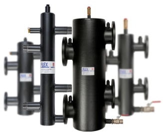
A Low Loss Header (LLH) is a Hydraulic Separator – it is a device that allows one part of a hydraulic system to work independently from another part, particularly necessary with multiple, pumped circuits operating together.
The function of the low loss header is to separate the two systems: primary heat source(s) and secondary loads. It allows equipment to operate at a constant flow rate in the primary circuit whilst flow rates and temperatures may vary in the secondary circuit.
This avoids any interaction between the two circuits and enables the primary circuit return temperature to represent the load on the system. It also permits return temperature sequence control of multiple heat sources.
How is hydraulic separation achieved?
The hydraulic separation is achieved by providing a very low velocity – hence very low pressure differential – path between connections within the low loss header body. This allows any difference in flows between the circuits to bypass through the body without influencing the characteristics of either the primary or secondary.
What are the benefits of a Low Loss Header?
Heating (or cooling) systems will typically contain multiple pumped circuits – multiple heat sources and multiple heating circuits. As any pump will naturally search for an operating point on its own curve, multiple pumps will tend to interact leading to unbalanced and unstable flows to each part of the system.
The benefit of this hydraulic separation is improved efficiency and performance of the heating system. Heat sources are safeguarded from irregular flows, ultimately increasing the life of the equipment. If installed vertically, the low flow velocity within the low loss header will allow dirt to separate to the bottom and air to the top of the body for easy removal.
Key design features of a Low Loss Header
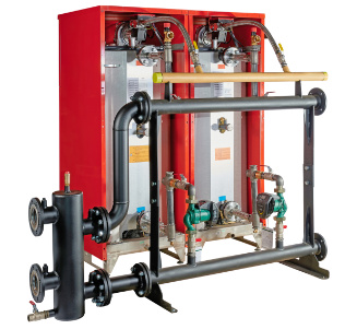
Both these features ensure a low pressure drop in the body and thus good hydraulic separation.
The connections to the LLH body are generally made at the same diameter as selected for the circuit piping. We recommend the use of horizontal headers as discussed below.
Vertical LLH are typically designed to include an AAV at the top and dirt valve at the bottom.
What Are Horizontal Headers?
Horizontal Headers refer to the preferred way the multiple primary and secondary circuits connect to the low loss header as shown below:
Alternatively each circuit may be connected to the LLH body independently – without horizontal headers – with one pair of connections for each circuit. The potential issue with this approach is unforeseen flow patterns in the LLH body. Given the purpose of the LLH is to provide a very low resistance path between connections some system conditions may give rise to undesirable flow between circuits.
Horizontal headers solve this problem by bringing together similar circuits into one connection to the LLH body. This ensures the expected flow pattern within the LLH regardless of variations in individual circuit flows.
All FlexEJ’s standard designs are intended for use with horizontal headers – we are happy to quote and build any required design.
How do you calculate the size of a Low Loss Header?
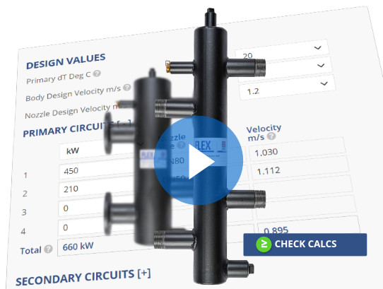
The calculator covers both connection schemes by providing 4 separate primary and secondary inputs plus a total which represents the horizontal header implementation. Fixed standard values for the properties of water are assumed when converting from power to flow rate.
Are there temperature changes with a Low Loss Header?
Yes – depending on the flow rates. As the low loss header works by allowing mixing of flow and return there must be a change in temperature of the mixed flow. Referring to the diagrams below, in all cases the flows in and out of the primary circuit must be equal so F1=F3 and in all cases the flows in and out of the secondary circuit must be equal so F2=F4:
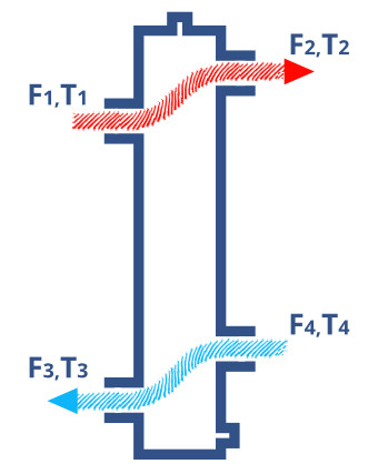
Case 1: Primary = Secondary flow
As the system is balanced there is no vertical flow in the LLH body so F1=F2 and necessarily F3=F4.
As a result the Primary flow temperature is equal to the Secondary flow temperature so T1=T2 and T3=T4.
There is no mixing.
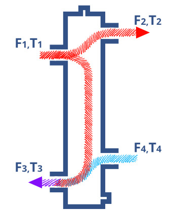
Case 2: Primary > Secondary flow
The simplest version of this case is when there is no secondary flow at all – so all the primary flow has to go through the LLH body and into the primary return.
For all other conditions where F1>F4 a proportion of the flow equal to F1-F4 goes through the LLH body.
The mixing is only at the primary return so T3 will need to be considered:
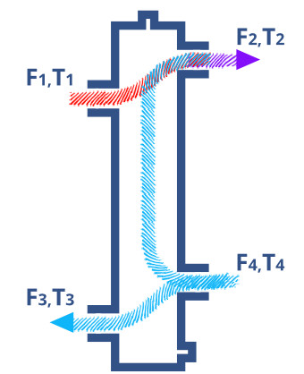
Case 3: Secondary > Primary flow
The simplest version of this case is when there is no primary flow at all – so all the secondary return has to go through the LLH body and into the secondary flow.
For all other conditions where F4>F1 a proportion of the flow equal to F4-F1 goes through the LLH body.
The mixing is only at the secondary flow so T2 will need to be considered:
Do FlexEJ have their own range of Low Loss Headers?
Yes. FlexEJ have a range of standard sizes.
You can choose from to order direct from this website or over the phone – and we also manufacture to your specifications for one-off orders as well as OEM suppliers.
FlexEJ standard LLH are designed for use with horizontal headers. All products are available from our web shop and ship from stock.
Please follow the link to the product page for full details, prices and shipping.
Can FlexEJ custom manufacture Low Loss Headers?
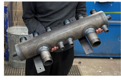
Yes we do. We offer short lead times on manufacture of bespoke low loss headers for use without horizontal headers – individual circuit connections to the body – and any additional features you require.
Please use the form below to contact us or call 01384 881188 to talk to our technical sales team.
